
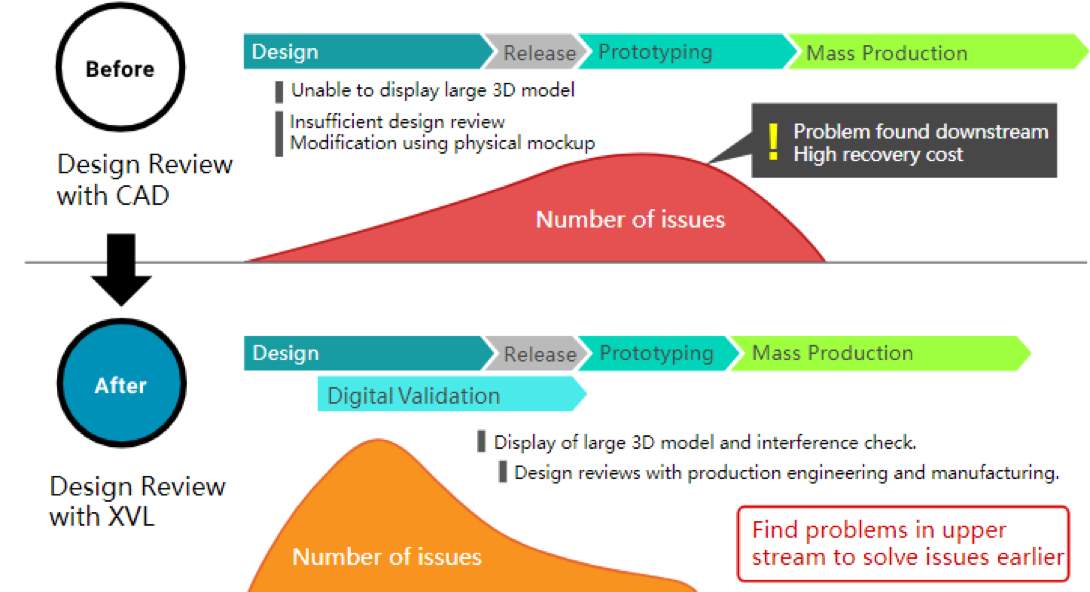
By performing design review using accurate and light-weight XVL 3D models, it is possible to identify in advance the problems that are missed when using 3D drawings. Using XVL for design reviews in production engineering and manufacturing enables you to find and fix problems before the model is released and avoid costly rework.
Many manufacturing companies used 2D paper drawings for design review in the past. Today, 3D CAD models are commonly used for design reviews. If you do a design review using 3D CAD models, you should be able to catch many of the problems that were missed in the paper drawings.
However, since 3D CAD data is extremely heavy, while you can view 3D models of smaller assemblies, it is usually not easy to view 3D models of the entire product. Therefore, if you intend to use 3D CAD models in Design Review, you will not be able to use the entire product assembly model, and the efficiency and accuracy of the review will be reduced.
In order to perform design review using 3D CAD models , it is necessary to use a 3D CAD workstation and a license for 3D CAD software. Both the workstation and the CAD license are expensive. You also need extensive training to use the CAD software effectively.
Therefore, considerable investment is required to provide a design review environment using 3D drawings. While it makes sense to make this investment for designers to use 3D CAD for day-to-day work, it is difficult to justify in terms of ROI for non-designers to use 3D CAD system just for design review purposes.
Undetected Problems in the Released Model Cause Rework
Interference, contact and clearance issues - these should all be found and fixed before the model is released. If these issues are not found by design reviews, they will cause problems later and require expensive rework to fix. That can delay product delivery and increase costs.
Also, since it is difficult to review the entire model at once using 3D CAD, most companies review parts of the model independently. This can result in missed issues when the parts are put together.
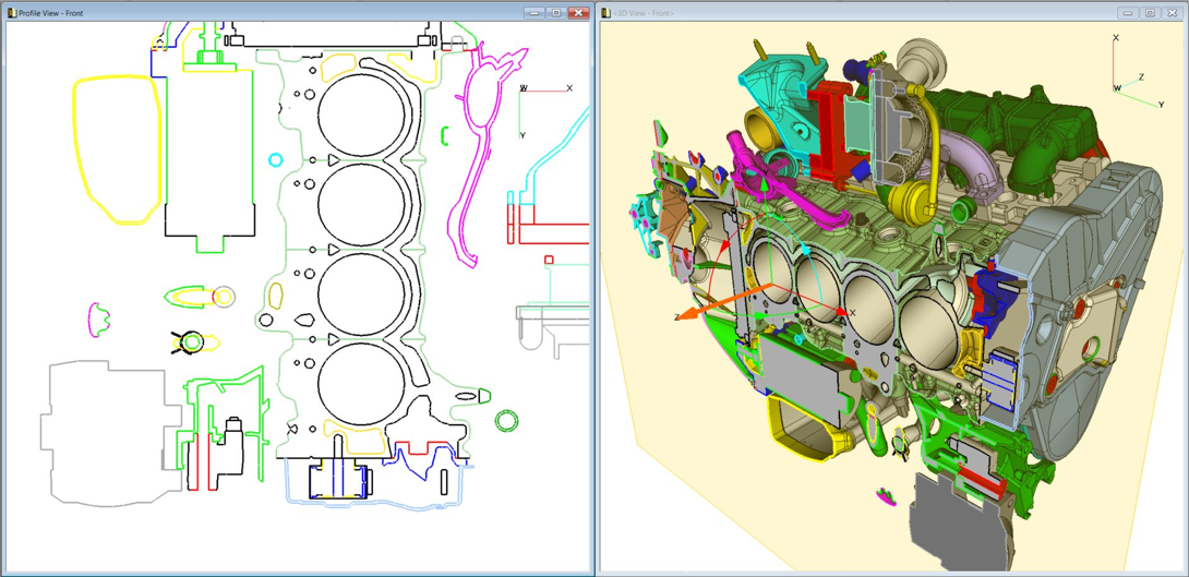
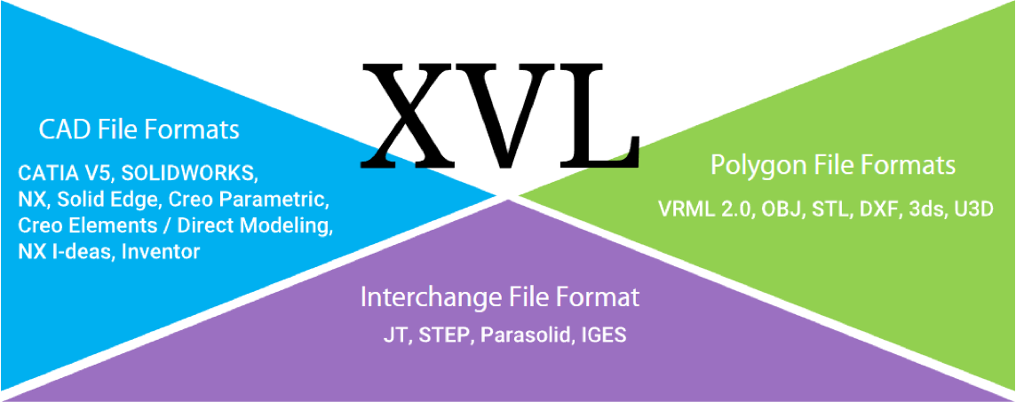
ASFALIS XVL, the world's highest-performance ultra-lightweight 3D format developed by Lattice Technology features extremely low data size. XVL reduces the 3D CAD data to 1% of its original size while maintaining accuracy of up to 0.001 mm. In addition, large-capacity 3D data can be manipulated smoothly with reduced memory consumption.
XVL can handle entire 3D product models – model that are too heavy for 3D CAD systems. This enables design reviews using the entire 3D model that find all of the issues – even those between different subassemblies. And XVL is so fast and easy to use, the it’s possible to perform frequent design reviews to improve the quality of the model – even in downstream departments.
ASFALIS XVL 3D models are available to anyone with standard computers and XVL products. No need for expensive 3D CAD software or high-performance workstations. With a standard PC or laptop and XVL products, you can quickly perform design reviews using 3D models.
If your design department uses several type of 3D CAD software, you can combine them into a single XVL model. As a result, design review environments can be developed at a much lower cost than using 3D CAD software.
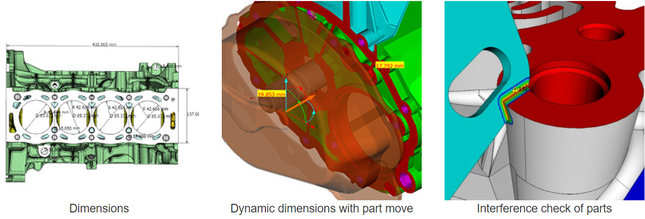
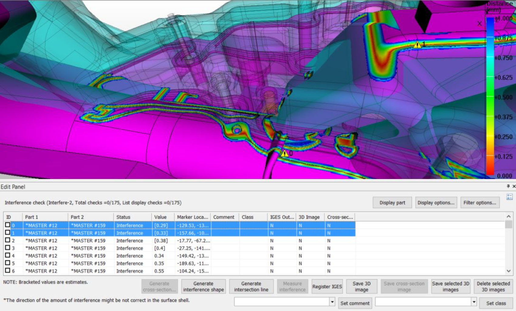
With ASFALIS Studio Pro, you can automatically detect interference, contact, and clearance between parts on XVL 3D models.
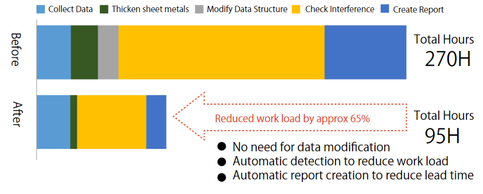
Using this function, it is possible to perform the kind of automatic verification of large models that is just not possible with 3D CAD systems. All issues are detected automatically and listed with detailed information.
In this way, all issues found in the XVL model can be easily reviewed and resolved by the design team – before the model is released. This reduces costly rework, reduces costs and shortens time-to-market.
Converting heavy 3D CAD data to lightweight XVL and adding manufacturing process information enables you to visualize and validate the entire assembly process. In this way, you can perform virtual assembly validation in XVL without waiting for the completion of design and without prototypes. Finding and fixing assembly problems early, before the design is complete, improves product quality, reduces the number of prototypes, reduces the time and cost of rework and shortens the lead time from development to production.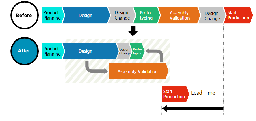
Traditionally the production engineering department performs assembly validation on physical models after all the parts have been designed and prototyped. Therefore, the more time it takes for design and prototyping, the later the assembly validation starts. In order to reduce the development lead time, it’s critical to remove the delay and start assembly validation as early as possible.
During assembly validation the production engineering department answers such questions as: "Can the parts be assembled properly in order", "Are there any interferences between parts or tools in the assembly process" and "Do the tools and jigs function properly?" If an assembly problem is found at this stage, fixing the issue usually requires a redesign and a new prototype. Needless to say, this rework is expensive and takes a lot of time.
Even if a complete assembly validation is performed on the final released design, the challenges do not stop there. It is always possible that there will be last-minute design changes. When that happens, it’s necessary to perform additional assembly validation on the updated design. With increased pressure to get the new design into production, there may not be time to do a thorough analysis, especially it the assembly validation process is slow or cumbersome.
Supports multiple bills of materials, so you can include manufacturing BOM (mBOM) and process data in addition to the original 3D CAD engineering (eBOM) structure. The BOMs can be cross-linked and associated with geometry and part data.
With ASFALIS XVL you can add process information to your 3D model without changing the engineering structure. This enables you to perform assembly validation on the model while it is still being designed. There is no need to wait for final release, or even for a complete model, to begin your assembly validation.
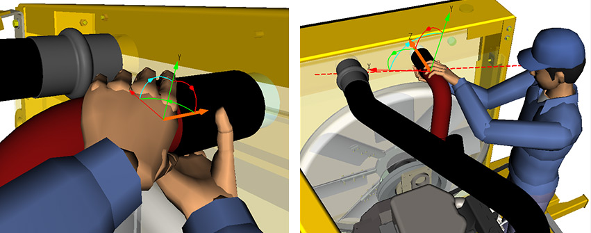
You can verify the assembly process steps, check for interference and clearance between parts, and even check jigs and tools – all without prototypes. In addition, you can use human mannequins to check the visibility and clearance of each operation.
Generate assembly issue reports, complete with 3D visualizations, as feedback to the designers. Then validate the updated design using XVL. By repeating this cycle over and over, you can improve design quality up front, even before the design is complete. A better quality design requires fewer prototypes, less rework, lower costs and faster lead time.
With XVL, you don’t have to start each assembly validation from scratch. XVL can carry forward validation results from previous models into new versions. So when you find an issue, report it back to the designers, and receive an updated model, you have all of your previous work for reference. Instead of validating the entire model, you can focus on only what changed. This enables you to accelerate your validations and get to production even faster.

Manufacturing instructions are usually created using mockups after all design, prototyping and assembly verification has been completed. Therefore, if delays or rework occur during the design or assembly verification process, the creation of manufacturing work instructions will also be delayed. In order to reduce the development lead time, you want to start at an earlier stage, but it is not always easy to start creating manufacturing instructions using the pre-released design data.
In order to create easy-to-understand manufacturing instructions, it is necessary to use multiple images and photographs to document the precise operations. However, the work of creating images, taking pictures, collecting them and inserting them into the document is extremely time-consuming.
When design changes occur, updating the work instructions is also a manual process. It requires new drawings and photographs, as well as manual work to change the instructions. To do it correctly requires knowledge of the design intent, the manufacturing process and the documentation itself. It is high-skilled, precise work. For major updates, it may be faster to recreate the work instructions from scratch.
At overseas production sites, linguistic and cultural barriers can make work instructions difficult to understand. Work instructions that rely on text, pictures and verbal information may not accurately convey the original intent to audiences with different backgrounds and experiences. As a result, production errors and rework can increase the cost of overseas production..
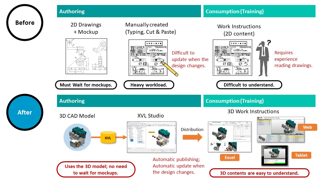
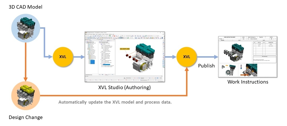
With XVL, you can automate the creation process of manufacturing work instructions by utilizing 3D model and its manufacturing process data. Since XVL does not require mockups, you do not have to wait to begin the authoring process. You can start authoring work instructions as soon as the 3D model is available. In this way, XVL enables you to front-load the authoring process and shorten production lead time.
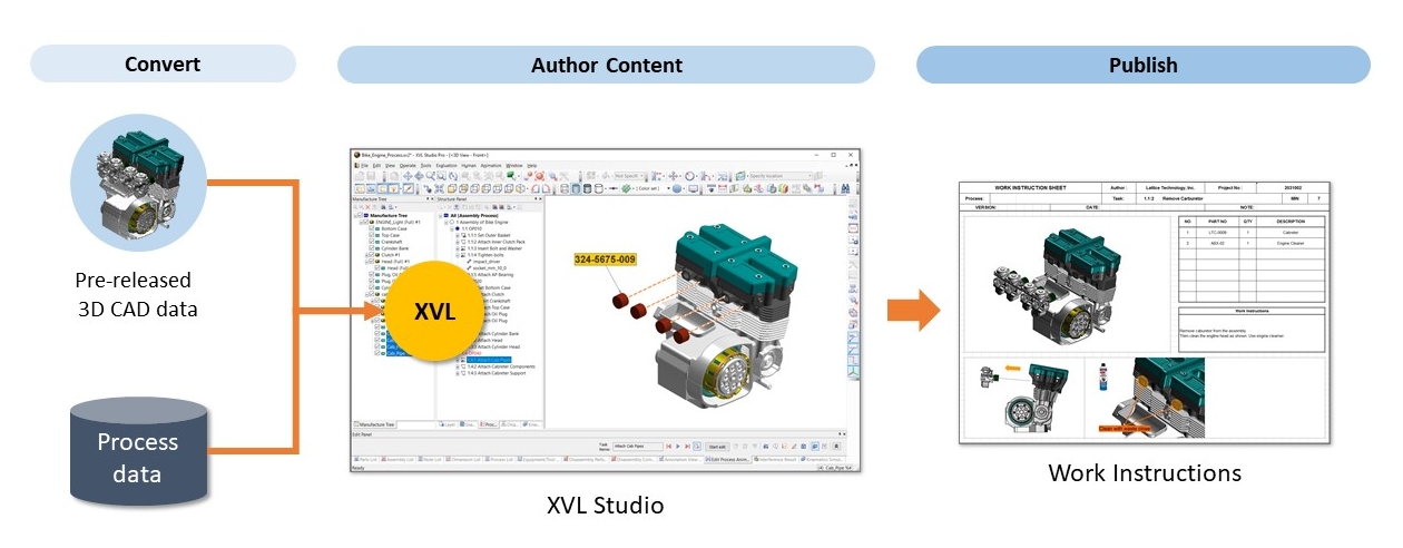
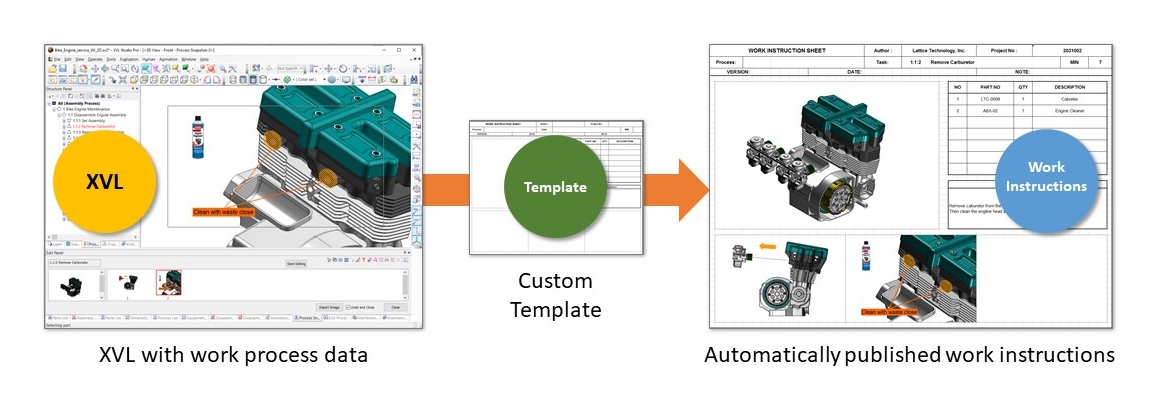
With XVL, you just need to create the work instruction document template. XVL tools will then automatically insert the 3D models and process data to publish the final document. This significantly reduces authoring time compared to manually creating and arranging images and typing work procedures.
XVL-based work instructions can be published in multiple formats for multiple platforms. Create online instructions in HTML and WebGL. Create offline documents including 2D and 3D PDF and Microsoft Excel spreadsheets. From a single XVL model, you can publish work instructions for viewing on PCs, mobile devices and even paper.
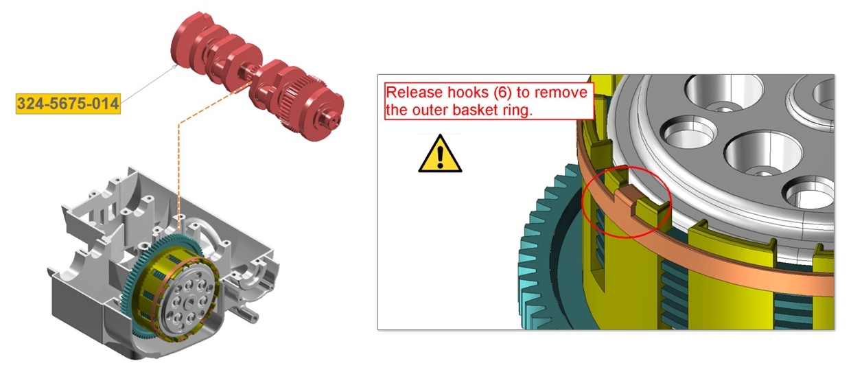
Providing clear manufacturing instructions to overseas production sites can be a challenge. Language and cultural barriers can make it difficult to convey subtle nuances of assembly processes, especially in text. XVL enables you to create visual work instructions with images and 3D animations. You can also add text, photos and markups as needed to clarify the intent. Rich, visual instructions transcend language and cultural barriers and are easier to understand, reducing production errors and making them the ideal work instructions for overseas production sites.
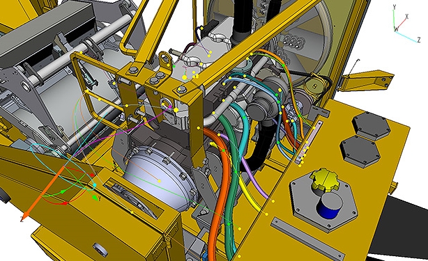
3D CAD models often do not contain wire/harness information. With XVL Studio, you can add wires/harnesses to your XVL model. This makes it possible to visualize the harness installation procedures in your XVL-based work instructions.
Usually, illustrations and figures in technical documents are created manually using actual products and photographs, at considerable time and cost. XVL can create technical illustrations directly from the 3D model, enabling you to start the process early. Also, XVL can automatically generate technical illustrations, taking care of the common cases so that it does not require specialized skilled technical illustrators, which can lead to the cost reduction.
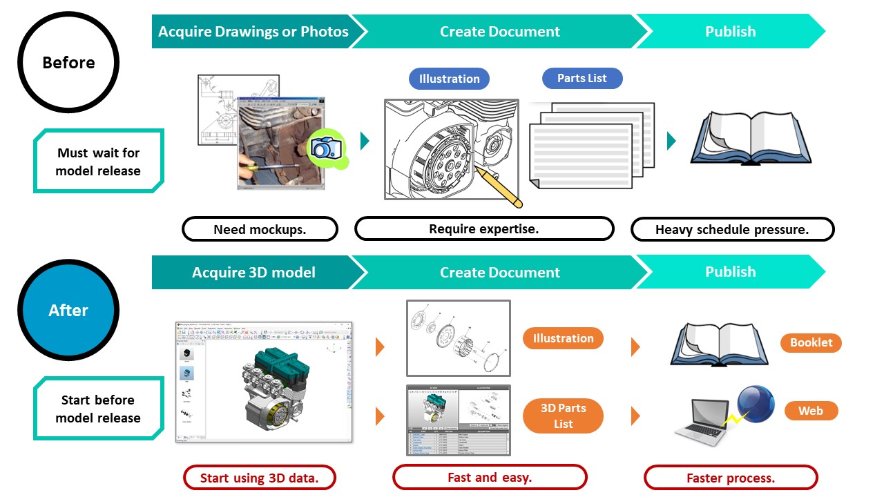
Technical illustrations are usually created based on drawings and photographs actual products. Therefore, illustration creation cannot start until drawings and products, or at least mockups, are available. As a result, illustration production starts late in the development process, resulting in heavy schedule pressure for the illustration department. The late start also makes illustration creation a bottleneck for efforts to reduce development lead time.
Technical Illustration Requires Expertise
Creating technical illustrations from drawings and photographs requires specialized skills and expertise developed with years of experience. And even for experts it can be a slow process. This further increases the pressure on technical illustrators and risks schedule delays.
Illustration quality can vary between illustrators, resulting in inconsistency in the resulting illustrations. It is important to maintain consistently high quality in technical documents, but such inconsistency cannot be completely eliminated when relying manual processes.
Creating Technical Illustrations and Documents is Expensive
Demand for technical illustrations and technical documents is increasing. With the recent trend toward high-mix low-volume production, the number and types of technical documents keep increasing. In recent years, more and more companies are making products that differentiate themselves not only in product development and sales but also in the quality of after-sales service. In order to implement such a strategy, it is essential to produce high-quality service documents. Manual illustration and document production processes have high labor costs, and the costs are only increasing.
With XVL, you can create technical illustrations directly from 3D models. There is no need for drawings or photographs, and no need to wait for physical products or prototypes. So you can start early and eliminate the bottlenecks that accompany late-cycle technical document production.
Furthermore, the XVL models can include more than just geometry – they can include manufacturing and service BOM data, notes, dimensions, images and much more. From illustrated parts lists to complete service manuals, XVL contains all the data you need to generate high-quality technical documentation.
XVL can automatically generate technical illustrations of parts and assemblies. It can also generate assembled or exploded views with or without links to parts lists. This automatic generation capability reduces the need for technical expertise in the manual production process.
Using 3D data to create technical illustrations can produce more consistent illustration quality than manual processes. Whether you lay out each illustration by hand, or use the automatic tools to produce multiple illustrations, using XVL to generate your illustrations enables you to standardize the illustration output parameters and maintain consistent quality throughout the department.
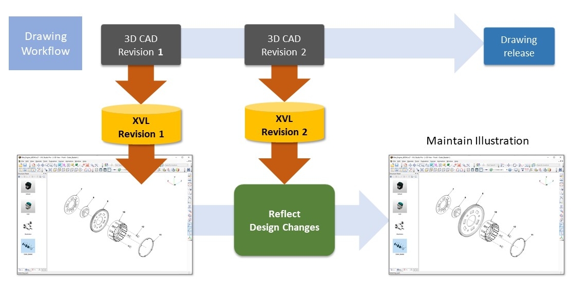
With XVL, it’s just as easy to update technical instructions as it is to create them in the first place. Design changes are automatically reflected in the XVL model, and the new model can be used to generate new technical illustrations.
As demand for technical illustrations and technical documents increases, XVL is there for you. XVL’s publishing tools enable you to generate the high-quality technical illustrations and documents you need, without breaking the bank.
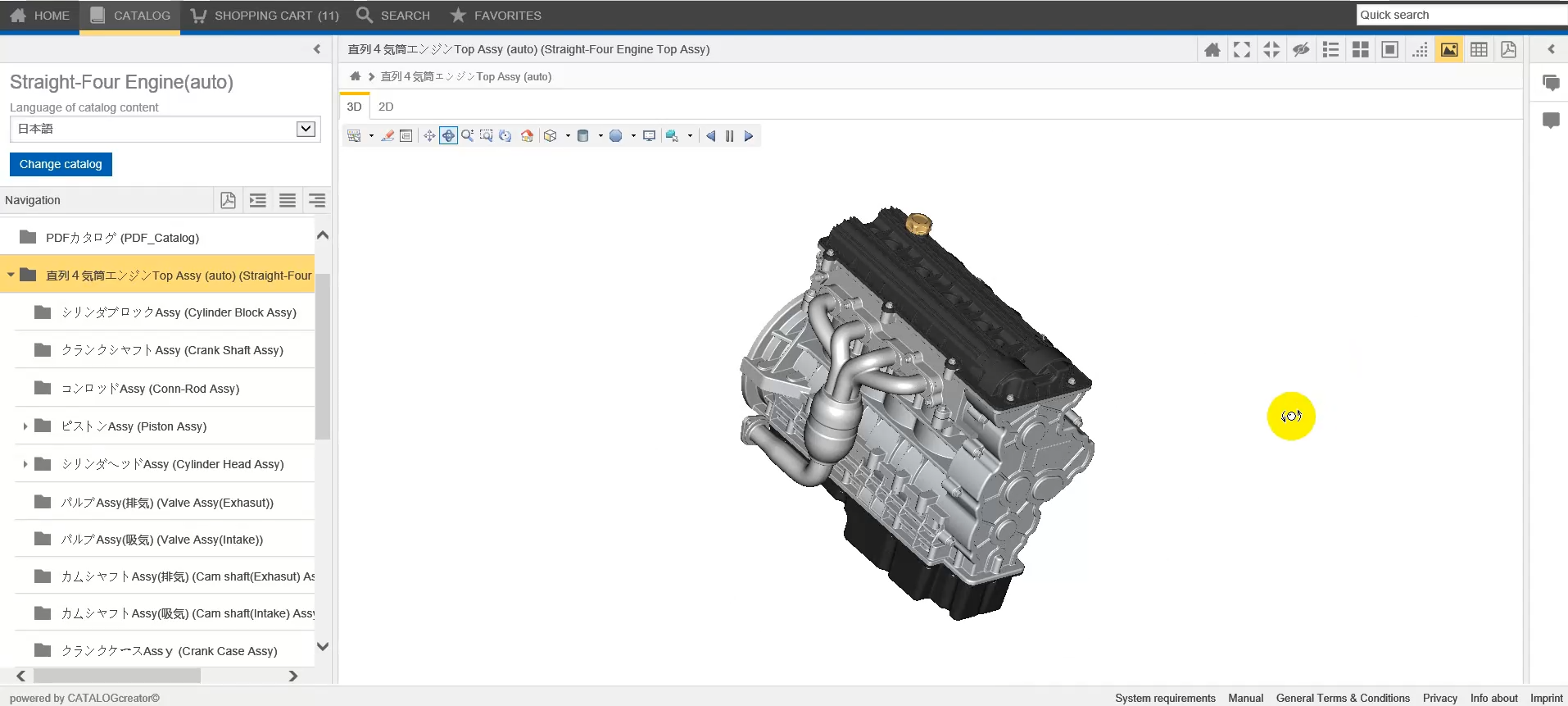
Extend the use of your 3D models into service and support. For example, electronic spare parts catalogs and service portals benefit the following stakeholders:
These solutions may contain information integrated from multiple sources such your MCAD and ECAD solutions as well as from your data repositories such as your ERP, PDM or PLM systems.
At Lattice Technology, one of our goals is to enable our customers to provide solutions to their stakeholders to identify the right part to order.
The reasons companies chose XVL for producing their spare parts catalogs include:
In addition to providing an interactive, graphical-based parts catalog, you can also provide all of your service procedures as interactive work instructions with these advantages: